How
to Install
ATI ProCharger (supercharger)
on a 350Z ('03 or '04)
Installation
Phase
Brackets
and Supercharger
Pages
24 and 26, Steps 1, 5, & 6: Ensure
all pulleys and idlers spin freely on the main bracket.
If they don't check that you've installed the spacers correctly.
Check the torque on all bolts on all brackets as you install
each one (torque specs are on page 2). You can also reference
illustration C5 on page 26.
Page
28, add a new step after Step 7: Check the oil
drain plug so that it is not too tight. If it is too tight,
you will not be able to get a wrench on it to drain the
oil. You may want to buy a new plug with a slightly thicker
head to make getting a wrench on it easier. An alternative
for draining oil is a suction device supplied by ATI to
suck oil out the oil filler hole on top.
Page
30, Steps 9 - 13: Pay close attention to these
steps, they can be tricky. Step 11 (installing the compressor
bracket) in particular can be tough. When positioning the
compressor, ensure the discharge hose is properly routed
before tightening bolts.
Page
32, Step 14: Ensure the IVT wires are free of the
compressor drive pulley flange; zip tie the wires securely
out of the way of the flange.
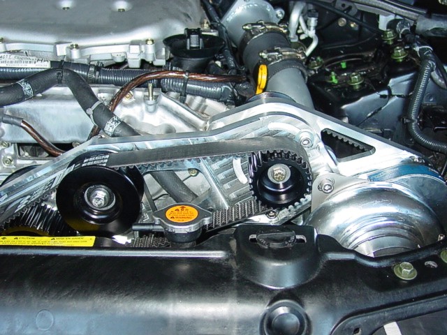
Page
32, Steps 15 and 17: We can't emphasize correct
alignment and tensioning of the two cog belts enough. If
the belts are too loose or do not run true, you will destroy
the belts quickly; too tight and you will burn up pulley
bearings. We know of one professional (paid) installation
where the cog belts were too loose and the belts were destroyed
within a week. As simple as it may sound, we've also seen
ProCharger installation photos (the installation obviously
done by amateurs) where the belts are not correctly routed—double-check
correct routing of all belts.
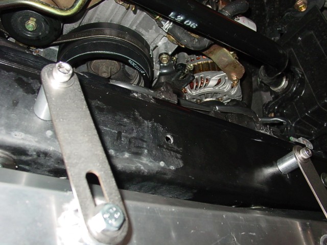
Page
34, Step 20: The serpentine belt is difficult to
tension because there is no adequate distance to properly
check tension. The best place to check tension is between
the alternator and power steering pump pulleys. Do this
from under the car when tensioning the belt. It may appear
too tight, but you should only be able to twist the belt
about 20-25 degrees. You'll know if it's too loose when
you start the Z and get belt squeal. Increase tension in
half-turns of the tensioning bolt until cold start-up squeal
disappears. Do not overtension the belt. Leave the lower
engine cowl off until you get the belt correctly tensioned
over a couple of days. With the lower cowl left off, ensure
the fender fairings are fastened to the front fascia. Note
all this information on page 55, step 29.
Page
34, Step 22: You can easily do this step later.
If so, annotate it on page 55, step 30.
Fuel
System and Fuel Management Unit
Caution:
Remember
there will be fuel in the line when you disconnect it: stay
clear and use a container to catch the fuel. Read the information
at the beginning of this section in the manual carefully.
Take note that since the auxiliary fuel pump is a DC motor,
you can make it spin in either direction which is why you
have to pay very close attention to the correct positive
and negative electrical connections.
Page
37, Illustration D3: Study this schematic carefully,
and lay out your parts as shown in the schematic so you
know how they will fit together. The label at the bottom
center of the diagram should read "Stock Fuel Line
To Fuel Rail." Obvious, but the "Barb Tee"
arrow doesn't point to the barbed tee. The way the fuel
pumps work is when the auxiliary fuel pump pressure exceeds
the pressure from the stock fuel pump, flow from the stock
fuel pump is directed only to the auxiliary fuel pump.
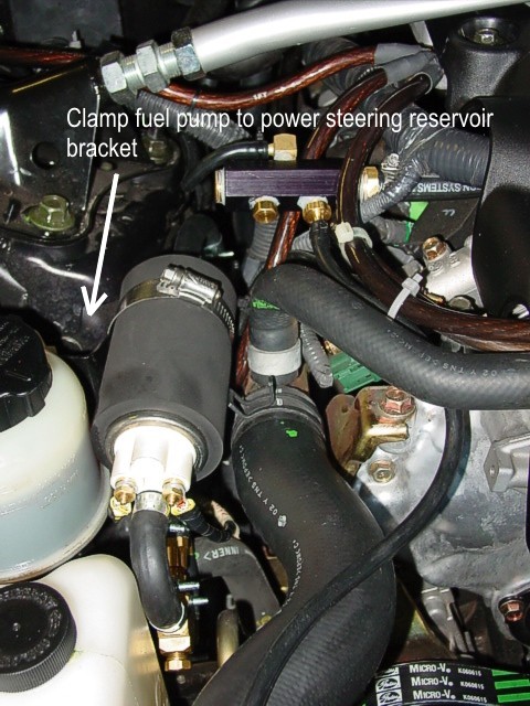
Page
37, Illustration D4: The fuel pump is not installed
in the position shown. Look at Illustration D5 for the correct
installation location. the pump clamp goes around the power
steering fluid reservoir bracket. Also in Illustration D4,
you will see a braided stainless steel line connected to
the cross fitting. Do not look for this line in your kit—it
goes to an optional fuel pressure gauge.
Page
37, Step 9: You can defer this step to page 52
when you do the rest of the PCV/vacuum line connections.
We preferred to do the PCV/vacuum connections all in the
same procedure so we didn't miss any part of this crucial
process.
Page
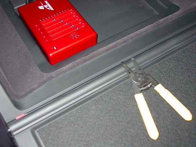
40, Step 11: We selected a different orientation
for the EFMU installation. Our orientation gave us a cleaner
installation, minimized wasted space in the glove box tray,
and is oriented toward the driver's seat—easier to
read when seated in the driver's seat.
Page
41, Illustration D8: We used a T connector and
higher quality electrical connectors throughout the installation.
The supplied connectors tend to crack when crimped. Our
connectors have a softer, pliable plastic shroud. These
are readily available at almost any good auto parts supply
store. It was pretty easy for us, because we already had
bags of better connectors in our tool box. Alternatively,
you can solder your connectors and then tape them.
Wire
and Vacuum Line Routing from Engine Bay to the Glove Box:
You'll notice that the manual doesn't really address this
step. Tape the ends of the vacuum hose, the red 10 gauge
wire, the black 10 gauge wire, and the yellow 12 gauge wire
together with electrical tape. This will allow you pull
all four together during routing. Straighten out about 10'
of the hose and wires so there are no kinks. If you want
a professional looking harness use harness tape starting
from about a foot from the end of the wires—two people
can do this very quickly; one holds a section taut while
the other wraps. Above the fusebox on the firewall in the
battery compartment, you will see a large rubber boot where
the main wiring harness passes through the center. We carefully
cut a slot just in front of the main harness large enough
for our wire and hose bundle to pass through. Make sure
you hit the large hole under the boot where the main harness
is. Pass about 10' of your hose/wire bundle through the
hole. Note, you only have 10' of vacuum hose; we added a
connector and another 3' of hose. At the connector, the
hose is zip tied. The connector is at the rubber boot, so
it keeps the vacuum line from being crimped. You'll find
that the bundle drops right to the passenger side floor.
Unclip the door sill, the front sill, and the first part
of the rear sill. Unhook the carpet hooks under the sills.
You will note a white plastic protector next to the seat;
the hose to the rear window washer runs through it.. Pull
this out and thread your bundle through it. Reinstall the
plastic protector. Snap a section of plastic wire loom around
your bundle where it comes down through the top of the firewall,
and run it down to the white plastic protector. Tuck it
in the neat little groove on the side of the passenger side
floor. Snap the rest of the wire loom on the bundle from
the white plastic protector to the end. Route the bundle
up through the opening to the glove box (the glove box tray
snaps out). Tape about a foot or so of the red 18 gauge
wire from the ignition source to your wire bundle so you
have at least a foot or more of free wire when you remove
the tray. Replace the carpet and sills, and proceed to page
42, step 10.
Page
42, Step 15: If you deferred step 9 previously,
leave the end of the vacuum line near the plenum area. You
will hook it up to the tee when the tee is installed.
Add
a New Step: Check continuity of all your wiring
with an Ohm meter. If you don't have one, you'll have to
wait until later to check continuity when you have the battery
hooked up.
Note:
We also wrapped our wires in the engine compartment to give
it a more finished, professional look.
PCV/Vacuum
Note:
Since
it is easier to install the PCV/vacuum lines at this point,
we skipped over to page 52, PCV Installation section. The
reason is, if you install the intake tube to the throttle
body, you will have to remove it to do the PCV lines. Refer
to page 44, Illustration E1, and lay out all your PCV/vacuum
parts so you can see how they fit together. You will note
that notations in steps 20 - 25 on page 52 are confusing
and not quite correct. Remember, doing this section right
is a very critical step, so make sure you understand thoroughly
how everything hooks up. Serious engine damage could result
if done incorrectly. Make sure all hose connections are
securely clamped or zip tied so nothing can pull loose.
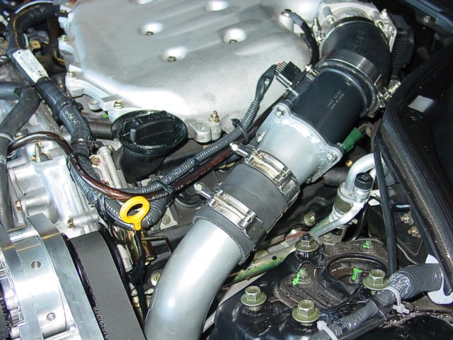
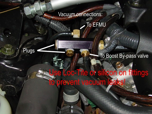
Preassemble
the vacuum tee fittings (page 37, step 9). Use Loc-Tite
when you assemble the fittings on the tee—it is critical
that you do not have any vacuum leaks in your fittings;
engine damage could result. In our assembly, it was preferable
to use the brass 90 degree fitting to connect to the vacuum
line going to the EFMU. See the tee connector photo on the
right.
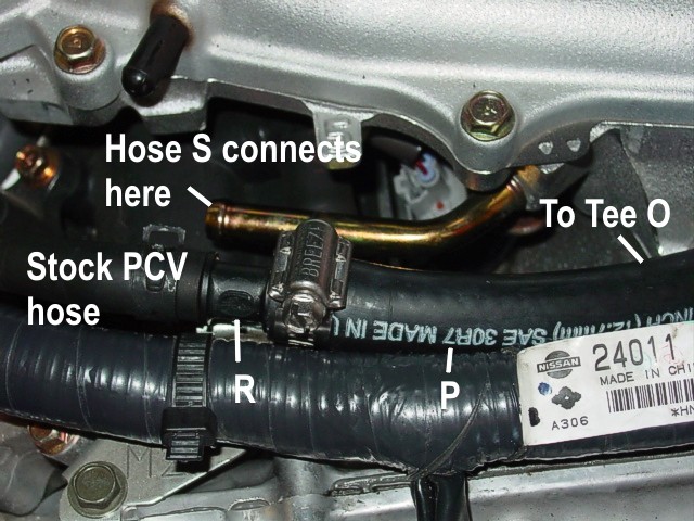
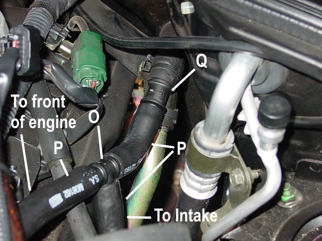
Page
52, Steps 20 - 25: Note that we will use the annotations
in Illustration E1 on page 44 rather than the annotations
in Illustrations E15 , E16, and E17 (they are wrong). In
Illustration E15, change 1/2" to 3/8" Reducer
to part R, and change Supplied 1/2" PCV Hose to part
P. In Illustration E16, change Supplied 1/2" PCV Hose
to part P in three places, and change 1/2" Tee to part
O. In Illustration E17, change 1/2" Hose Section to
part P and 5/8" to 1/2" Reducer to part Q. Also
see the accompanying photos on the left and right—click
the photos to see annotations corresponding to Illustration
E1.
20.
Connect 1/2" Tee (part O) to hose (part P) and connect
other end of hose to reducer (part R).
21.
Connect reducer to stock PCV hose at left front of plenum
(as you're looking at engine from the front). You'll remove
the hose from it's stock fitting at the front of the plenum.
22.
Connect 1/2" hose section (part P) to 1/2" Tee
(part O) and install the 5/8" to 1/2" reducer
(part Q) to the other end of the hose using supplied clamps.
Connect reducer (part Q) to the factory 5/8" PCV hose.
Illustration E17 with noted changes.
23.
Connect 1/2" hose section (part P) to 1/2" tee
(part O).
24.
Route the other end of hose under the compressor and out
and up to where the air intake tube (part U) will be. When
the intake tube is installed, attach the hose to the fitting
in the tube.
25.
Hose S connects to the vacuum tee fitting and runs to where
the stock PCV hose was connected at the front of the intake
plenum.
New
Step: From Page 37, Step 9: Take assembled vacuum
tee and connect to hose S in step above. Connect the vacuum
line from the EFMU to the 90 degree fitting. Connect the
vacuum line that runs from the tee to the bypass valve.
We ran our line forward over the radiator hose, and it fit
very neatly into the crevice on top of the fan shroud, then
it drops down to the front area below the headlight on the
driver's side where it will eventually be connected to the
bypass valve.
Now
go back to page 45 to complete the intercooler and piping
installation.
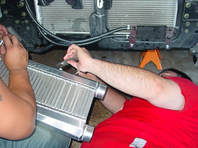
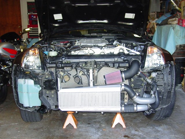
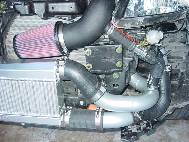
Intercooler
and Intake Piping
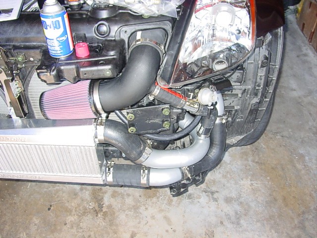
We
suggest installing the intercooler next, and then do all
the tubing last. This is so you can ensure all the tubing
lines up correctly. You may have to trim some of the rubber
hoses for a better fit. If you wish to do this then skip
over to page 48, and run Steps 6 through 9 for the intercooler.
Then complete all the rest of the piping starting on page
50, and run steps 10 through 12.
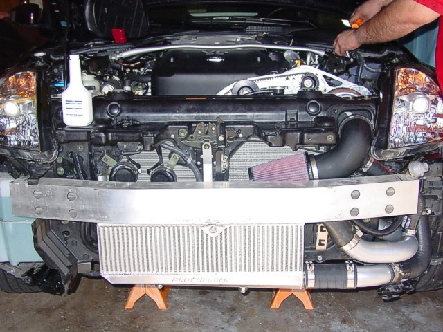
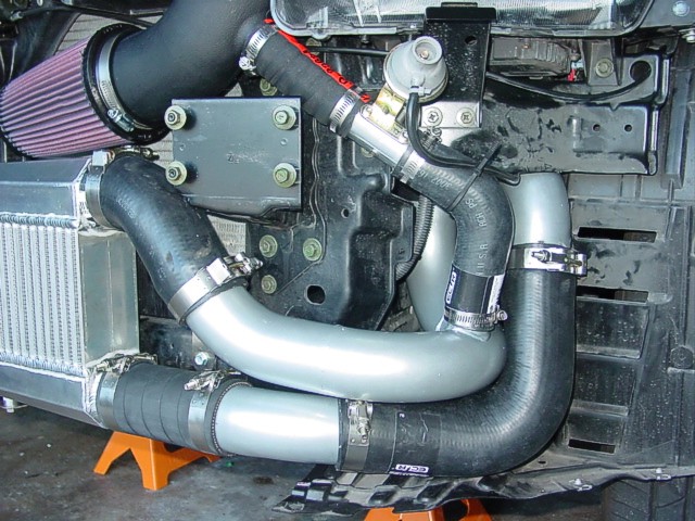
Page
50, Step 10: Bend the lower left corner of the
bumper bracket inward and up so that no sharp corner will
wear a hole in the upper tube on the intercooler.
Now
go back to page 45 and pick up with Steps 1 through 5.
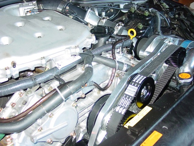
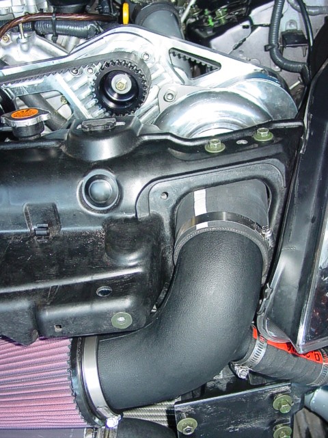
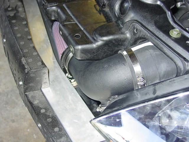
Page
45, Steps 1 & 2: Make sure the MAF sensor connection
is angled toward the plenum so that when the hood is lowered
it will not hit the connector. The way Illustration E2 shows
it, the connector wire will not be long enough. Refer to
out photo on the left side showing the MAF housing orientation
and connector. Attach the connector after the tube section
is installed.
Now
jump back forward to page 50, and pick up steps 13 through
19.
Page
50, Step 15: You will have to do a little twisting
and turning of all the tubing pieces to get the best fit.
Once you've got everything to your satisfaction, tighten
down all the hose clamps.
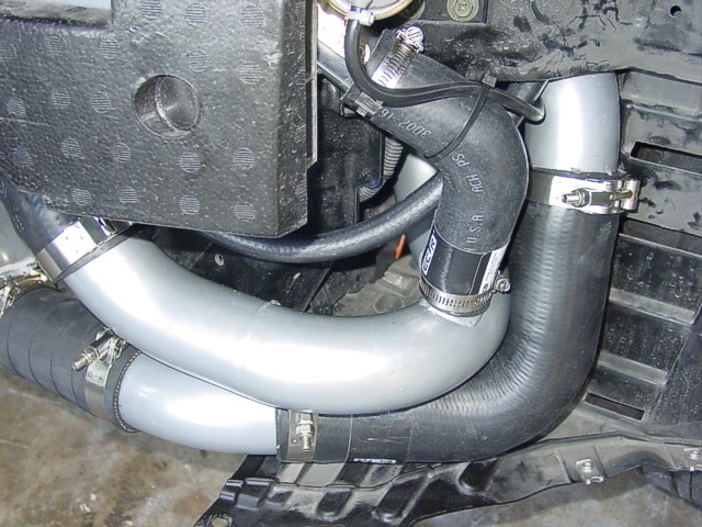
Page
52, Step 18: We routed our vacuum line in the crevice
at the top of the fan shroud. We believe it's a much better
routing than that suggested in the manual.
Once
you've competed step 19, jump forward to page 55.
Add
a New Step: Here is where we reinstall the upper
right front fascia bracket that goes across the compressor
inlet tube. We removed it and set it aside in step 21 on
page 12. Note that you will probably have to cut out a curved
portion on the back of the bracket to get a good fit around
the intake. There's a photo on the right that shows how
the bracket is cut (not pretty, but functional).
Page
55, Step 29: You may want to leave the lower engine
cowl off for a couple of days in case you have to adjust
the serpentine belt tension.
Page
55, Step 30: Trim the engine cover to fit around
the supercharger brackets and front cog belt. We used a
saber saw to rough cut and then precision high-speed grinding
tool with a small, fine grinding bit.
Add
a New Step: Check everything again, and then go
back and check it again.
Add
a New Step: If you haven't previously checked your
EFMU wiring continuity, be sure to check it after you've
hooked up the battery.
Add
a New Step: Set the EFMU settings to starting settings
listed on page 58, item 2.
Add
a New Step: Put oil in the supercharger!
Add
a New Step: Put power steering fluid in the reservoir.
Then go do step 38 on page 22.
Phases
(click on a link):