Notes
on kit instructions:
-
Enclosed
parts are different than listed in the enclosed instructions
parts list.
-
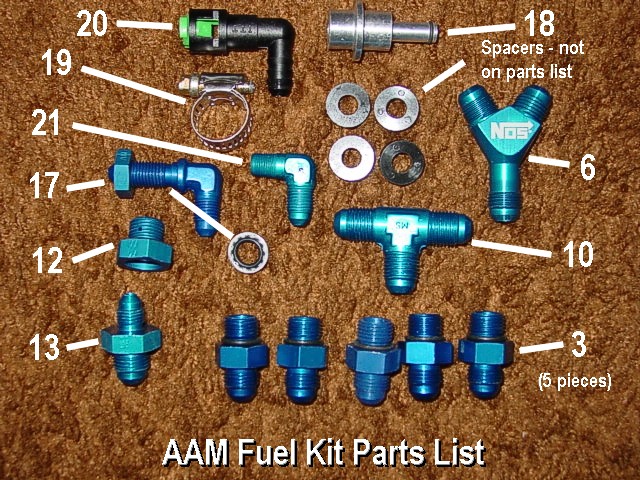
All
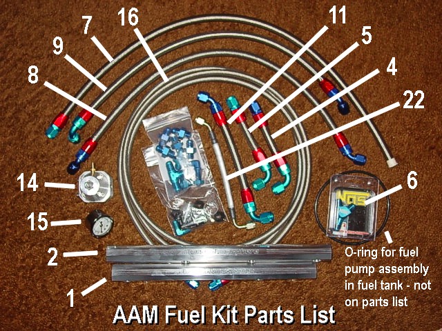
instructions reference the parts by number, and you will
have to refer to the parts list (see photos left and right).
-
Instructions
are incomplete and missing a few key details - in fact,
there are some serious information gaps.
This
article clarifies and expands on the kit instructions. Pictures
for parts are included and referenced to the part numbers
in the instructions. Click on the photos on the left and right
to enlarge.
You
will need:
-
Metric
socket set, 3/8" drive
- Ratchets,
3/8" drive
- Extension,
3/8", 6" long
- Full
metric box/open end wrench set up to 21 mm
- Phillips
and flat-head screwdrivers, various sizes
- Pliers:
needle-nose, standard
- Dikes
to clip zip ties
- Set
of picks
- Allen
wrench set
- Loc-Tite
- Joint
tape
- Floor
jack
- Jack
stands (2)
- Trays
to hold nuts and bolts
- Zip
ties: large, medium, small
- Vacuum
line: 2' and T connector
- Shop
rags of course
- Two
hose clamps and connector
- Optional
06 AN connector/adapter from pressure regulator to fuel
pressure gauge sending unit
Procedure:
1.
Remove fuel pump fuse (inside battery box on firewall fuse
box - remove cowl pieces to access - fuse is on bottom, left
side)
2. Start engine and run until it stalls - this will relieve
most of the fuel pressure in lines
3. Disconnect battery cables (negative first)
4. Remove strut tower bar
5. Remove engine cover
6. Remove intake piping from throttle body - completely removing
an entire section is recommended - you may have to remove
the MAF connector as well, depending on your setup and what
you remove
7. Remove all wires and hoses attached to the upper plenum
- there are two coolant hoses going to the lower part of the
plenum near the throttle body that will be easier to remove
after the upper plenum is loose
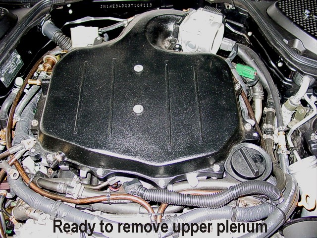
8. Remove all bolts and two nuts holding the upper plenum
in place - 10mm
9. Remove upper plenum - here is where you can easily remove
the two coolant hoses going to the bottom of the plenum near
the throttle body
10. Remove the fuel dampener assembly from the lower plenum
on passenger side - 10mm
11. Remove the hose from the front of the lower plenum
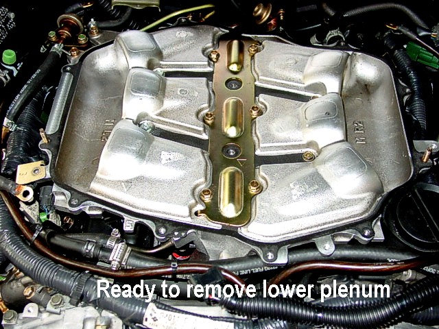
12. Remove the bolts from the lower plenum - 6 in the center,
and two nuts outside center front and rear - 10mm
13. Remove the lower plenum and cover the intake manifold
with shop cloth
14. Remove the two hoses from the fuel dampener assembly hardline
pass through
15. Remove the main fuel feed line at the quick disconnect
on the passenger side - may be easier to get at from the bottom,
in which case you will have to jack the front end up and drop
the under engine fairing - have a shop rag handy to catch
any fuel drips
16. Remove the injector wire connectors from the injectors
- pick the metal clips in order to remove the connectors (for
RC injectors, just push in on the metal clips)
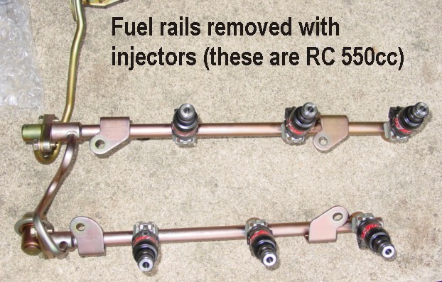
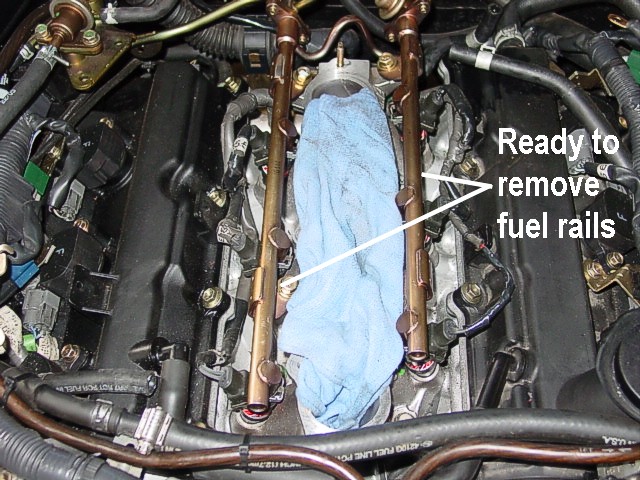
17. Remove the four fuel rail bolts - 12mm
18. Carefully lift up as straight as possible on the fuel
rails to remove - use care not to damage the fuel injectors
- watch for fuel draining from rails
19. Remove the fuel injector clips (use small flat-head screwdriver)
and pull injectors straight out - watch for fuel as you remove
the injectors
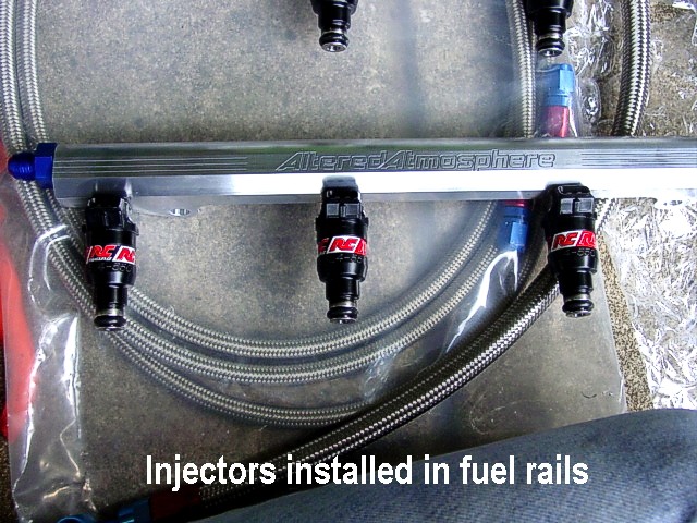
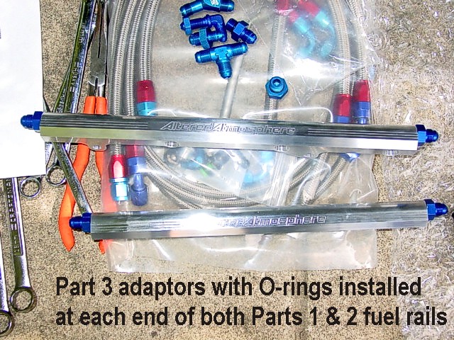
20. Install adapters (part 3) on both ends of each fuel rail
- use tape on threads.
21. Lightly lubricate the injector O-rings with clean oil
22. Insert injectors into rails - connectors go toward outside
of rail that has engraved lettering
NOTE: The instructions say to use the injector
clips - this is impossible with the RC 550cc injectors; you
cannot use the clips. I did not check fit of stock injectors.
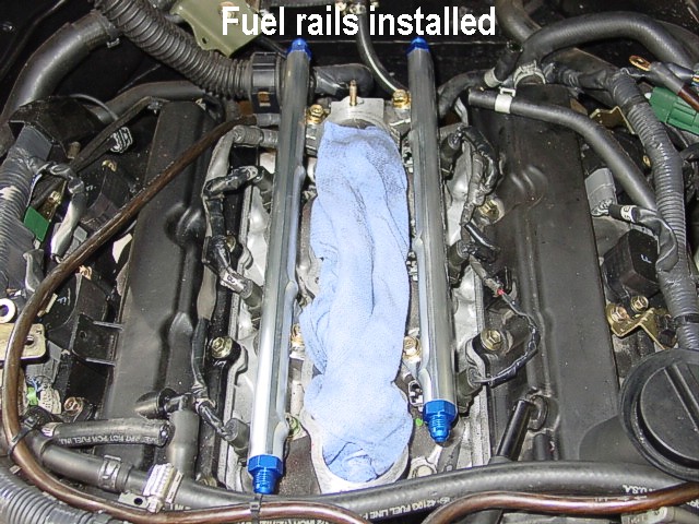
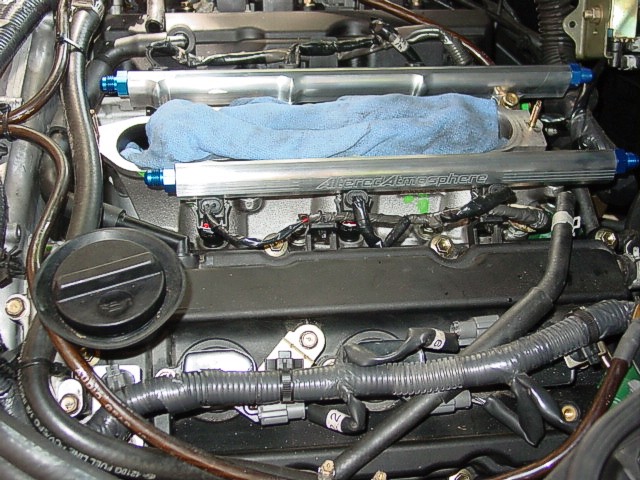
23. Install the fuel rails (longer one on passenger side;
shorter one on driver's side) - use care to press straight
in - connect electrical connectors and then replace four 12mm
bolts (with spacers for RC injectors)
NOTE: The supplied black plastic spacers
are 2.5 times too short for the RC 550cc injectors - use the
aluminum RC spacers.
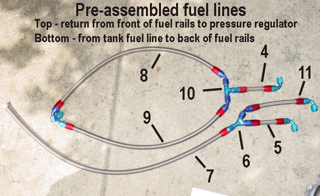
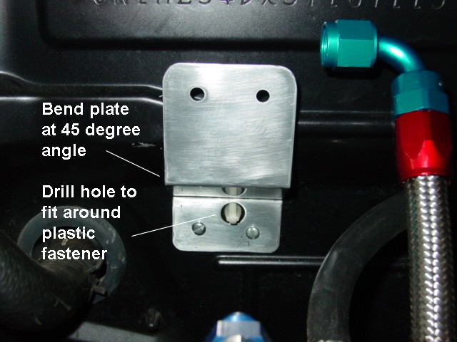
24. Pre-assemble the lines that will be installed at each
end of the fuel rails (see photo on left for line assembly
details - one picture is worth 1,000 words you know)
25. Install the return fuel line assembly - the 90 degree
connector installs on the passenger side and routes down the
driver's side valve cover - the 45 degree connector installs
on the driver's side and routes down the passenger side valve
cover
26. Injector harness ties were clipped off and harness and
fuel lines secured with large zip tie through the original
harness tie hole (shown in photo on right)
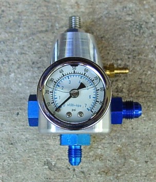
27. Pre-assemble the fuel pressure regulator components as
shown in photo
NOTE: You can replace the fuel pressure gauge
with a sending unit to a fuel pressure gauge in the vehicle
interior, or you can replace the plug with a 06 AN adapter
for the fuel pressure gauge sending unit and still use the
pressure gauge on the regulator (second option recommended).
28. Locate a suitable mounting point on the firewall for the
pressure regulator - you will have to put a couple bends in
the supplied regulator mounting bracket (it's just snipped
from thin sheet metal - you can fabricate a more substantial
and nicer bracket)
NOTE: Account for plenum reinstallation and
make sure the mounting point allows enough room -- you can
test fit the lower plenum to check mounting point suitability.
NOTE: If installing the Kinetix SSV intake
manifold, do not mount the fuel pressure regulator on the
firewall - shorten the fuel return line coming into the regulator
and fit the regulator into the space at the bend of the intake
pipe - see related article on Kinetix
SSV installation
29. Mark drill holes for the regulator bracket in the firewall
and carefully drill guide holes smaller than the mounting
screws - the screws are self-tapping - attach the mounting
bracket
30. Attach the return line assembly connector to the regulator
right side, under the vacuum line connector, and attach regulator
to the mounting bracket with supplied allen head screws (we'll
deal with the vacuum line on the regulator later)
31. Attach the pre-assembled fuel feed lines to the fuel rails
- the line routes off toward the passenger side from the fuel
rails
32. Attach the quick disconnect fitting with the supplied
screw clamp on the bare end of the fuel feed line (parts 19
& 20 respectively)
33. Connect the fuel feed line to the stock fuel line with
the quick disconnect connector - ensure the fuel line is secured
and well clear of the exhaust manifold
34. Attach the fuel return line to the bottom of the pressure
regulator and route down the passenger side near the fuel
feed line - ensure the fuel line is secured and clear of the
exhaust manifold
35. Remove glove box bottom piece, tray, and lining to expose
fuel pump assembly
36. Jack passenger side and place jack stands
37. Route the return fuel line through the existing fuel line
clips down the passenger side frame rail and follow the path
of the fuel feed line to the tank (you can use a wire to pull
the fuel line up next to the gas tank)
38. Remove the jack stands and lower the car
39. Remove fuel pump assembly from fuel tank: twist four cover
retaining clips 90 degrees - remove electrical connector and
them fuel line - remove screws and retaining ring - lift pump
assembly out carefully and avoid bending the fuel level float
arm
CAUTION: Before removing pump assembly, make
sure battery is disconnected and you ground yourself to car
to avoid static discharge and ignition of any fuel vapors
in tank - avoid fuel spillage by placing pump assembly in
shallow plastic pan - have a shop cloth handy to catch any
fuel seepage when disconnecting fuel line
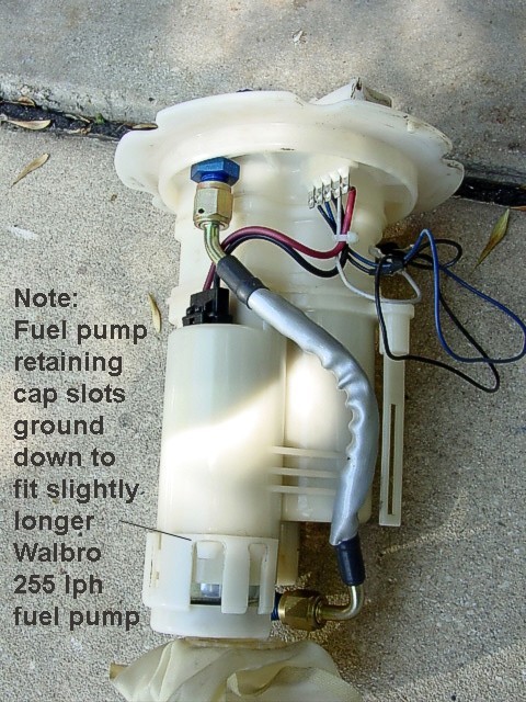
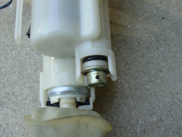
40. Remove the fuel pump assembly outer cover and drill a
hole in the top of the fuel pump assembly right above the
fuel pump - be sure to have clearance for the connector nut
- install connector as shown in the photo
41. Remove the stock fuel pressure regulator, preassemble
the new regulator bypass with connector as shown in the photo,
and press into pump assembly
42. Install the fuel return line between the two fittings
- ensure it is routed so it slides back into the fuel pump
assembly outer cover - slide the assembly back into the outer
cover
43. Reinstall the fuel pump assembly in reverse order as above
and again, be careful not to bend the fuel level float
44. Leave the fuel pump assembly cover off so you can check
for leaks when you pressurize the system
45. Reconnect battery cables (positive first)
46. Replace the fuel pump fuse and cowling
47. Turn the ignition on so that the fuel pump runs, and check
all lines for leaks - tighten fittings if necessary
48. Replace the fuel pump assembly cover, lining, and glove
box tray
NOTE: See related article on Kinetix
SSV intake manifold installation in lieu of steps 49-54
NOTE: New lower and upper plenum gaskets
are recommended
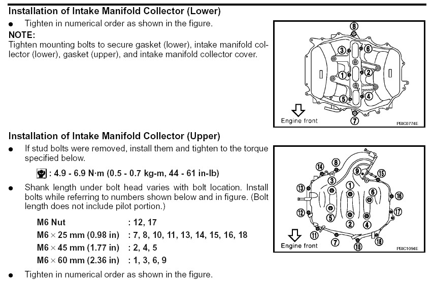
49. Replace the lower plenum - refer to service manual for
bolt tightening order and torque specs
50 . Connect the hose to the front of the lower plenum
51. Connect the two EGR lines that previously ran through
the fuel dampener assembly together with a connector and clamps
(additional parts you need to buy - AAM is supposed to add
a connector to the kit as a result of my feedback)
52. Replace the upper plenum - attach the two coolant lines
at the rear and then lower plenum into place
53. Tighten the upper plenum bolts/nuts in the order shown
in the service manual using torque specs
54. Replace hoses and wires previously removed
55. Locate a suitable vacuum port on the plenum (if you have
forced induction, you can T off your vacuum/boost gauge line),
and route your vacuum line to the vacuum fitting on the fuel
pressure regulator - clamp or zip tie the vacuum hose to the
connectors
56. Reinstall the intake and MAF connector
NOTE: If you previously removed the under
engine fairing, you can replace it now.
57. Go through and double-check that everything is hooked
back up correctly, and then fire that Z baby up
58. Tune the fuel pressure using the adjustment screw on the
top of the pressure regulator - unlock the screw with the
nut, and then use an allen wrench to make the adjustments;
51psi for a Z at idle is optimum - lock the nut when finished
adjusting
NOTE: If you set the idle fuel pressure too
high, the ECU senses an overpressure (around 65 psi) and will
shut the fuel injectors down - the old VQ35 will obviously
not run with the injectors shut down
Instructions
in Word document
Right click on link and select Save As
|